Brian wrote: ↑Tue Jul 11, 2017 5:20 pm
Ah that makes a great deal of sense that it would fail that way, and I remember in your writing a mention of angling the sides of the pin to increase the resistance to that twisting effect.
Actually, as regards to making
shachi sen which are in cross section rectangles, versus parallelogram in section, I think this is an interesting area worth a look in detail.
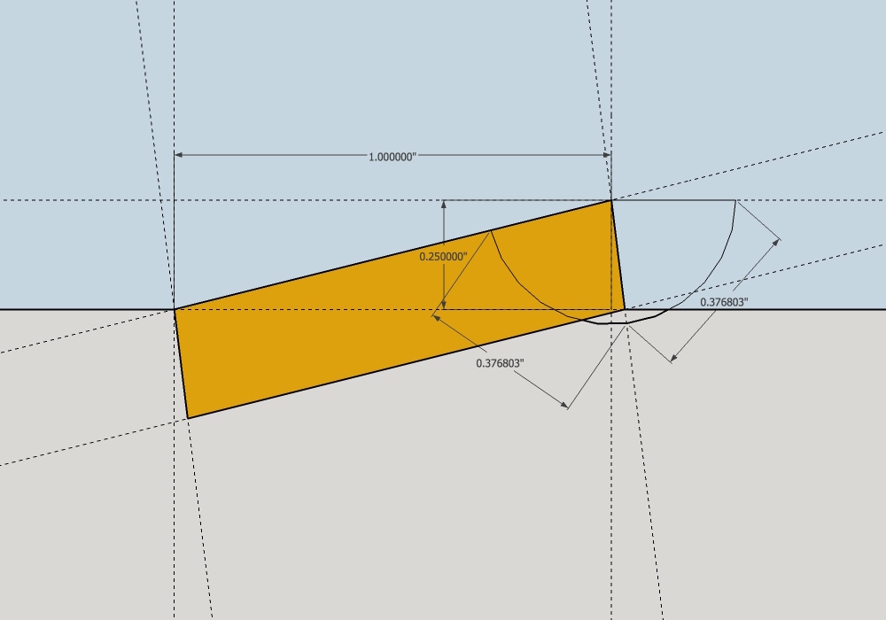
Let's examine first a rectangular-section pin, placed within the layout boundary lines of 0.25" for depth and 1.0" for length:
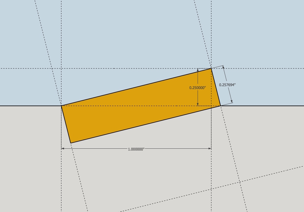
- rectangular pin.jpg (116.15 KiB) Viewed 6657 times
Note that if you employ those boundary lines and cut to them, the pin itself has to be about 0.0075" thicker than the nominal 0.25" it might appear to need to be otherwise. I chose to meet the depth line at the intersection of the 1.0" line, and projected over 90˚ from there back to the edge line,, and you can see we end up therefore over-running the 1.0 boundary.
One could choose to meet the boundary of 1.0" and edge line with the 90˚ corner of the pin, like this:
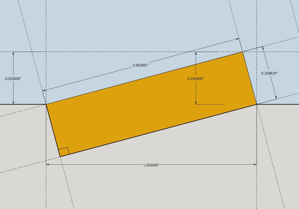
- rectangular pin II.jpg (135.3 KiB) Viewed 6654 times
In this case, the pin needs to be over-dimension for thickness and under-dimension for width to meet such a mortise. Using a stock 1.0"x 0.25" thick material for the pin in either of the above cases, and cutting to the marks results in mortise to tenon fits which are not as sweet as they could be. A cut out pitfall for those that inspect closely afterwards, perhaps.
When the rectangular pin is driven in, a portion of the load is transferred laterally outward into the receiving member, and we have seen what happens in those joints when stressed to failure and the rolling of the pins levers the side of the stick open until it splits.
The parallelogram-section pin can now be compared:
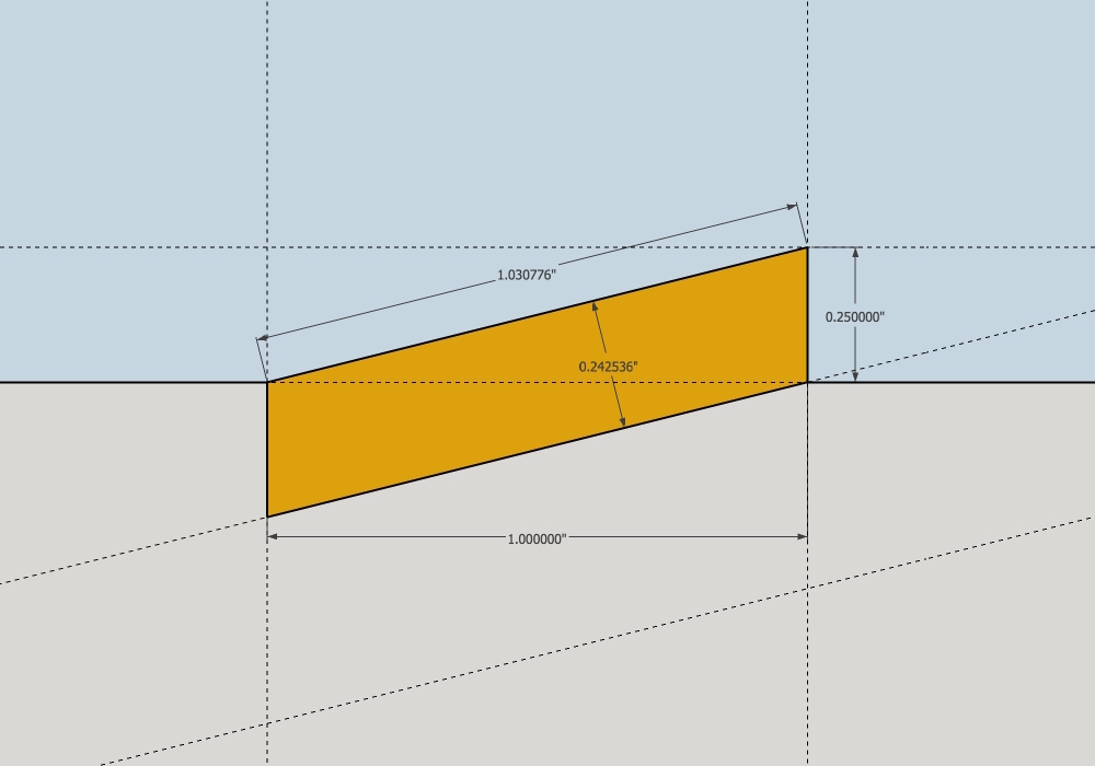
- parallelogram pin.jpg (110.39 KiB) Viewed 6657 times
The main improvement realized by the parallelogram is the load transfer directly into a 90˚ end grain abutment in the receiving piece, in parallel alignment to the grain of that piece. That appears strong and all, however there is a slight tendency now for the pin load to be transferred to shear the wood abutment away from the receiving piece inwards - longitudinal shear in other words. Pins for this situation are actually made about 0.0075" under the 0.25" thickness when you mortise to a 0.25" line of depth. If one didn't notice this, and made the pins exactly 0.25" thick, then they would be rewarded by a fitting situation in which the mortise, though cut to the lines, seems too tight for the pin you precisely sized (because it IS). If your cut out is sloppy anyhow, the foregoing is a moot point.
Another comment that could be made about the parallelogram arrangement is that the trench for the
shachi sen has an acute internal angle, and I dare say this is a little harder to cut cleanly than one with an obtuse angle. Jabbing or slicing hard into the tip of the acute interior angle more easily risks that the chisel will tend to cut a little deeper than you might like into the surrounding wood, and this can precipitate a split later when the joint is loaded. The acute internal angle also represents also a more concentrated point load than when the abutment is square.
I have tended to prefer the parallelogram pins in that past, though they do make for a slight increase the cut out difficulty over the rectangular, both in making the pins and mortises.
There is an argument (well, one I am at least making) for a middle position between the rectangle and parallelogram sections of shachi sen. It's a potential refinement. The argument for this approach being along the lines of those used for detailing the critical and highly-stressed heel joint in a truss, between the tie beam and the principle rafter, or chord, connecting to it on (the beam's) top surface: you ideally bisect the angle between the two and that bi-section sets the abutment angle in both mortise and shoulder on the connecting piece.
Here's what I mean, taking the same boundaries of 1.0" for width and 0.25" for depth
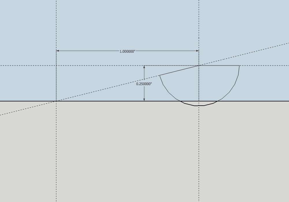
- perfect version.jpg (76.73 KiB) Viewed 6657 times
The angle in question is the complement to the one in a right triangle having a rise of 0.25" and a run of 1.0", namely 165.964˚.
Bisect that angle and you obtain the ideal middle ground abutment angle of 82.982˚:
- perfect version yes.jpg (125.29 KiB) Viewed 6657 times
And very conveniently, the required pin for this is exactly 0.25" thick. Cutting an 82.9˚ abutment is not a technical difficulty if you can cut them for the parallelogram-shaped pin and mortise shapes.