Page 3 of 4
Re: An investigation Begins
Posted: Sun Jun 19, 2016 10:03 pm
by Chris Hall
Hi Chris.
In direct answer to your question, the answer would be 'no'.
I consider double circular work to be the toughest level of technical carpentry, and if I wait around for a client to come along who wants that sort of work undertaken, I'd wager it would likely never happen. How would a client know to ask for that, if they are unaware of its existence or do not appreciate what it means? That's always the problem.
There's lots of things I want to build - carpentry is a vast art and I want to walk down most, if not all of the paths a good long way, to the point i feel like i understand the terrain in any given area.
Studying here is for the sake of study, the belief that learning new methods will open up new possibilities. I feel I have to put out the effort myself to get there to improve - and even if I never get a paid job to build a geometrical staircase or elliptical vault, say, I can at least feel like I have explored those topics and done it justice.
Learning about a specialized are such as this is, to my way of thinking, like acquiring a useful tool. Some tools we use every day, and some infrequently, but it sure is good to have the right tool when the need arises.
Re: An investigation Begins
Posted: Mon Jun 20, 2016 8:46 am
by Chris Pyle
Thanks Chris,
I appreciate the response. I didn't know if you had intention of exploring it in project form. Without your blog, I would've never heard of French Carpentry or art du trait or many, many other things. I hope we get to see this exploration translated into wood.
As an aside: I've been greatly enjoying your recent blog posts. Looks like the Zimmerman is earning it's keep.
Re: An investigation Begins
Posted: Mon Jun 20, 2016 9:49 am
by Chris Hall
Thanks Chris.
To be clear, while at the moment I am only studying drawing techniques, I do plan to build many of the study examples in the text as they occur. That's the only way to truly cement an understanding of the material. Several examples that are similar to the 'X Marks the Spot' project I detailed several years back on my blog are likely to be the first pieces to dig into.
Re: An investigation Begins
Posted: Fri Jul 08, 2016 12:31 pm
by Chris Hall
After the study of cylinders and cones, etc., I finally arrived at Plate 1, a study of a square section stick passing through a larger square section stick. The smaller stick is offset from the centerline of the larger stick and axially rotated at an arbitrary angle.
The problem shown relates to the 'X Marks the Spot' problem in some respects:
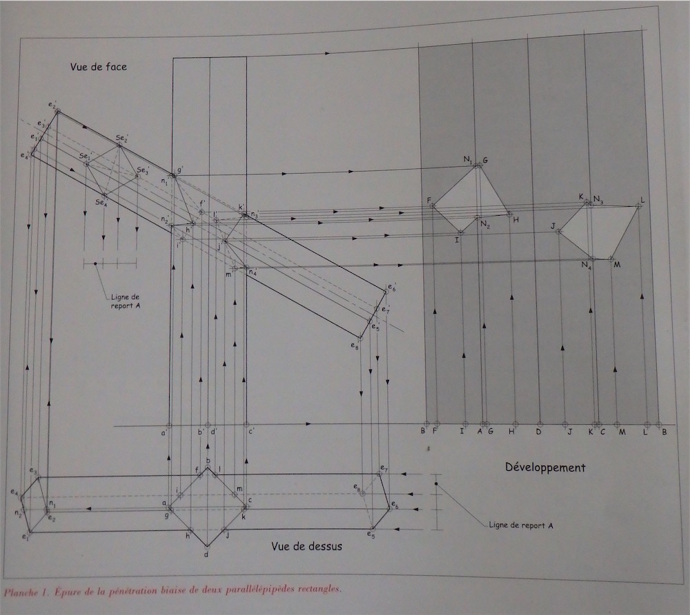
- P7080001-small.JPG (160.73 KiB) Viewed 6854 times
On the right of the picture is the objective, an unfolded view of the larger stick with the mortises marked out. The method, as drawn, does NOT produce a correct map of the mortise on the larger stick.
I drew it in Sketchup, following the 2D development in the text until I produced the view of the 4 faces of the larger stick. Then I rotated the panel up and folded it (like it were paper) into a stick. Then connected the lines within and checked out the result. It was not a mortise for a square-sectioned stick, but a skewed section, nor were the mortise dimensions correct in either axis.
Thinking initially that I had misunderstood something, I drew it all again, with the same result. Then I decided to reverse-engineer, from 3D back into 2D. In the end I figured out that the text shows an incorrect method, and this morning I have determined exactly what their mistake was. The drawing is 99% correct otherwise, but that one small mistake causes the unfolded view of the post mortises to come out utterly wrong.
Can you also find the mistake?
And, given that this is a Compagnons du Devoir official textbook on the topic, and it is plate 1 in the text, the first principal study, and that the drawings in the book were likely done by CAD anyhow - - how to account for this error in the book? Surely they are not making deliberate mistakes to confuse people....
Re: An investigation Begins
Posted: Sat Jul 09, 2016 12:39 pm
by Chris Hall
Planche 2 was correct. This is the layout of mortises on a cylinder to allow a square stick on slope, with arrises rotated to 45˚, to pass through:
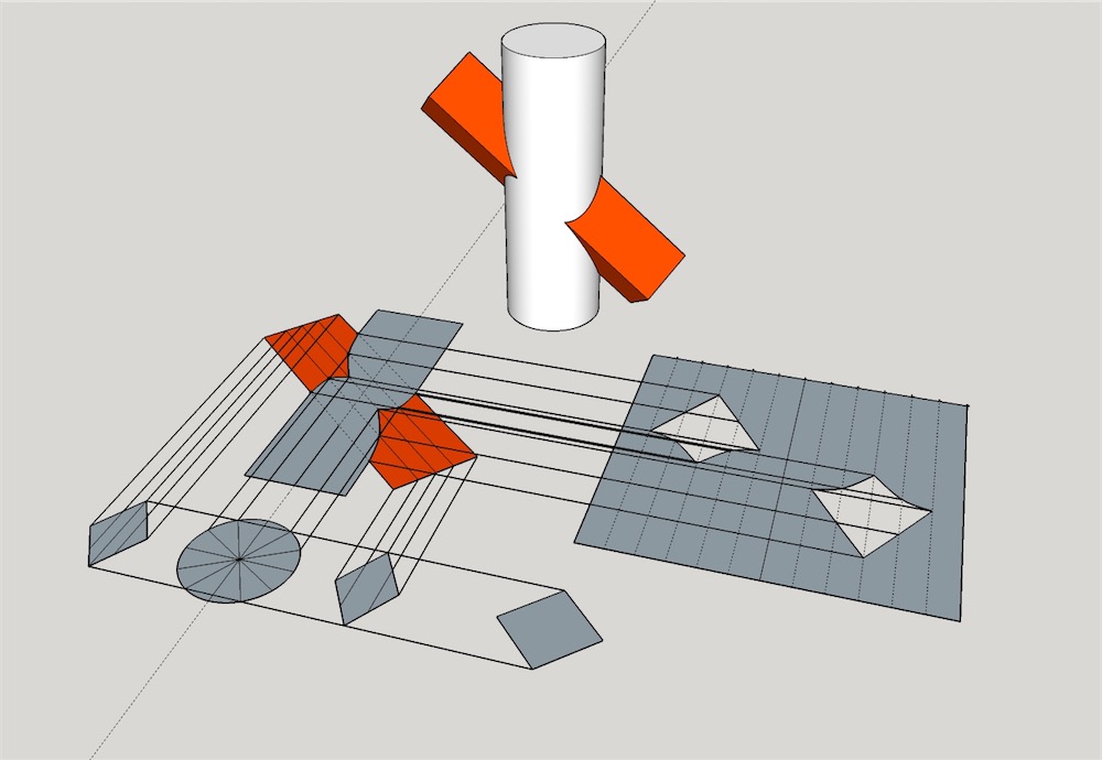
- Penetration 2-small.jpg (91.3 KiB) Viewed 6839 times
Though it would be perhaps more complicated to cut out than the preceding example, it was easier to lay out.
Re: An investigation Begins
Posted: Mon Jul 11, 2016 1:31 pm
by Brian
Interesting. I see it could have a practical application connecting to peeled posts but with some inconsistencies from the ideal.
Re: An investigation Begins
Posted: Mon Jul 11, 2016 9:06 pm
by Chris Hall
Of course, it is also useful to know this layout if your plan is to simply house the rectilinear stick on the cylindrical post on each side, rather than piercing though.
I've moved along a good ways in this section, completing another three studies. Here's one of them:
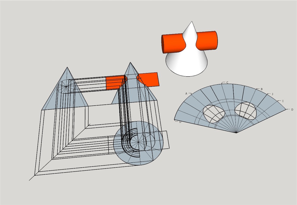
- Penetrations 3-small.jpg (98.63 KiB) Viewed 6814 times
Next up is an angled cylinder passing, but not completely contained within, a cone. Then it is a horizontal cone penetrating a vertical cone, and then cone and sphere intersecting, and the section will be compete.
Re: An investigation Begins
Posted: Tue Jul 12, 2016 6:52 pm
by Marc
Chris Hall wrote:Can you also find the mistake?
I didn't find the time to draw it so far, but the puzzle kept bothering me.
I was on the verge to say: There is no mistake!

But I hold my tongue and stared at the picture again.
Finally I spotted the mistake.

They mixed up the upper and lower arris while they transfer them from elevation view to plan view.
The horizontal measure from the cross section of the stick that passes through. (Ligne de report A)
You got me with the book, a few days ago I ordered my copy.

Re: An investigation Begins
Posted: Tue Jul 12, 2016 7:14 pm
by Chris Hall
Marc wrote:
They mixed up the upper and lower arris while they transfer them from elevation view to plan view.
The horizontal measure from the cross section of the stick that passes through. (Ligne de report A)
That's not quite it, if I understand you correctly, however the problem does indeed lie with 'Ligne de Report A'. The way they projected it is wrong and it leads to a plan view of the stick which is not the correct width. From there, all the projections involving that section will be erroneous.
Re: An investigation Begins
Posted: Thu Jul 14, 2016 11:22 am
by Marc
I think we both mean the same, but thanks to my poor English I was not able to explain it well enough.
So, a picture is worth a thousand words.
I numbered the corners/arrises of the stick (cross section) in elevation view and brought the horizontal measurements between these points with my "story pole" (Ligne de report A) to plan view. It is there where the mistake happend. In the original they confound number 2 and 4.
In my sketch I outlined the arrises of the stick (red colour) to show how it would look like in plan view if they hadn't made the fault.
Better now?
